Our website is made possible by displaying online advertisements to our visitors.
Please consider supporting us by disabling your ad blocker.
Beam tilt
This article needs additional citations for verification. (August 2009) |
| Part of a series on |
| Antennas |
|---|
 |
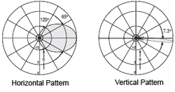
Beam tilt is used in radio to aim the main lobe of the vertical plane radiation pattern of an antenna below (or above) the horizontal plane.
The simplest way is mechanical beam tilt, where the antenna is physically mounted in such a manner as to lower the angle of the signal on one side. However, this also raises it on the other side, making it useful in only very limited situations.

More common is electrical beam tilt, where the phasing between antenna elements is tweaked to make the signal go down (usually) in all directions.[1] This is extremely useful when the antenna is at a very high point, and the edge of the signal is likely to miss the target (broadcast audience, cellphone users, etc.) entirely.
With electrical tilting, front and back lobes tilt in the same direction. For example, an electrical downtilt will make both the front lobe and the back lobe tilt down. This is the property used in the above example where the signal is pointed down in all directions. On the contrary, mechanical downtilting will make the front lobe tilt down and the back lobe tilt up. In almost all practical cases, antennas are only tilted down – though tilting up is technically possible.
The use of purely electrical tilt with no mechanical tilt is an attractive choice for aesthetic reasons which are very important for operators seeking acceptance of integrated antennas in visible locations.
In GSM and UMTS cellular networks, mechanical tilt is almost always fixed whereas electrical tilt can be controlled using remote actuators and position sensors, thus reducing operating expenses. Remote electrical tilt is abbreviated as RET and it is part of the Antenna Interface Standards Group's open specification for the control interface of antenna devices.[2]
Occasionally, mechanical and electrical tilt will be used together in order to create greater beam tilt in one direction than the other, mainly to accommodate unusual terrain. Along with null fill, beam tilt is the essential parameter controlling the focus of radio communications, and together they can create almost infinite combinations of 3-D radiation patterns for any situation.
- ^ Alexander, W.C. (6 November 2002). "Overshoots and Close-In Coverage". Radio World. Archived from the original on 3 August 2010. Retrieved 2009-08-14.
{{cite news}}: CS1 maint: unfit URL (link) - ^ "Archived copy" (PDF). www.torni.fi. Archived from the original (PDF) on 20 July 2011. Retrieved 12 January 2022.
{{cite web}}: CS1 maint: archived copy as title (link)
Previous Page Next Page


