Our website is made possible by displaying online advertisements to our visitors.
Please consider supporting us by disabling your ad blocker.
Transonic


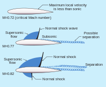
Transonic (or transsonic) flow is air flowing around an object at a speed that generates regions of both subsonic and supersonic airflow around that object.[1] The exact range of speeds depends on the object's critical Mach number, but transonic flow is seen at flight speeds close to the speed of sound (343 m/s at sea level), typically between Mach 0.8 and 1.2.[1]
The issue of transonic speed (or transonic region) first appeared during World War II.[2] Pilots found as they approached the sound barrier the airflow caused aircraft to become unsteady.[2] Experts found that shock waves can cause large-scale separation downstream, increasing drag, adding asymmetry and unsteadiness to the flow around the vehicle.[3] Research has been done into weakening shock waves in transonic flight through the use of anti-shock bodies and supercritical airfoils.[3]
Most modern jet powered aircraft are engineered to operate at transonic air speeds.[4] Transonic airspeeds see a rapid increase in drag from about Mach 0.8, and it is the fuel costs of the drag that typically limits the airspeed. Attempts to reduce wave drag can be seen on all high-speed aircraft. Most notable is the use of swept wings, but another common form is a wasp-waist fuselage as a side effect of the Whitcomb area rule.
Transonic speeds can also occur at the tips of rotor blades of helicopters and aircraft. This puts severe, unequal stresses on the rotor blade and may lead to accidents if it occurs. It is one of the limiting factors of the size of rotors and the forward speeds of helicopters (as this speed is added to the forward-sweeping [leading] side of the rotor, possibly causing localized transonics).
- ^ a b Anderson, John D. Jr. (2017). Fundamentals of aerodynamics (Sixth ed.). New York, NY. pp. 756–758. ISBN 978-1-259-12991-9. OCLC 927104254.
{{cite book}}: CS1 maint: location missing publisher (link) - ^ a b Vincenti, Walter G.; Bloor, David (August 2003). "Boundaries, Contingencies and Rigor". Social Studies of Science. 33 (4): 469–507. doi:10.1177/0306312703334001. ISSN 0306-3127. S2CID 13011496.
- ^ a b Takahashi, Timothy (15 December 2017). Aircraft performance and sizing. fundamentals of aircraft performance. Momentum Press. p. 107. ISBN 978-1-60650-684-4. OCLC 1162468861.
- ^ Takahashi, Timothy (2016). Aircraft Performance and Sizing, Volume I. New York City: Momentum Press Engineering. pp. 10–11. ISBN 978-1-60650-683-7.
Previous Page Next Page


